8 Bit Adder Circuit Diagram
Vhdl tutorial – 21: designing an 8-bit, full-adder circuit using vhdl Adder bcd cheggcdn Logic gates
11+ 4 Bit Adder Circuit Diagram | Robhosking Diagram
8 bit adder circuit 6.4: 2-bit adder circuit Full-adder circuit, the schematic diagram and how it works – deeptronic
Adder circuit diagram schematic bit full works figure
Adder fitfab circuitsFitfab: 8 bit adder truth table Adder circuit logic using digital boolean implementation diagram implement functionDigital logic design: full adder circuit.
11+ 4 bit adder circuit diagramAdder bit circuit Adder adders circuits libretexts pageindexAdder vhdl designing 8bit compile simulate waveform verify program.

Download 4 bit adder circuit stick and logic diagram
Adder bit circuit half make logic diagram comparator gates first electronics questions cout second only connecting solved puzzle which stack .
.


VHDL Tutorial – 21: Designing an 8-bit, full-adder circuit using VHDL
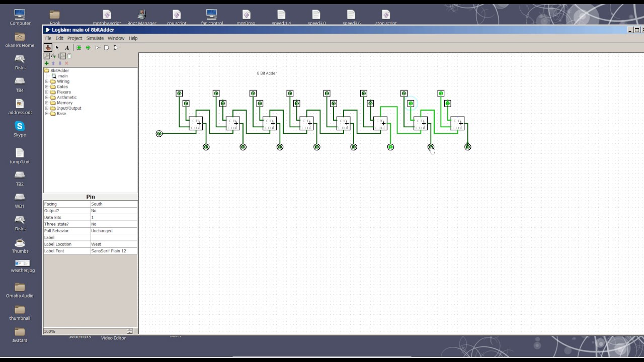
8 Bit Adder circuit - YouTube

Digital Logic Design: Full Adder Circuit

Download 4 bit adder circuit stick and logic diagram - Educative Site

11+ 4 Bit Adder Circuit Diagram | Robhosking Diagram

Fitfab: 8 Bit Adder Truth Table

Full-Adder Circuit, The Schematic Diagram and How It Works – Deeptronic